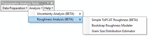
The Bootstrap Roughness Modeler Tool is located under the Analysis menu and under the Roughness Analysis sub-menu:
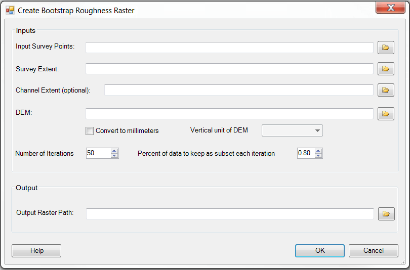
When the Bootstrap Roughness Modeler is run, the following dialog appears:
A video tutorial for how to use the Bootstrap Roughness Modeler can be seen below:
INPUTS:
The inputs for this tool are:
- Input Survey Points
- Point feature class of the points used to create the digital elevation model (DEM) used as input below.
- Survey Extent
- Polygon feature class representing the extent of the survey.
- Channel Extent (optional)
- Polygon feature class representing areas not to be included in the bootstrapping. For example if a channel unit polygon feature class is used as input then the bootstrap will only be performed using points that exist outside of the channel unit feature class.
- DEM
- Digital elevation model (DEM) that was created from the input survey points.
- **Convert to millimeters **(optional)
- if this check box is selected then the output results will be in millimeters (useful for flume data)
- **Vertical units of DEM **(optional, only enabled if Convert to millimeters is checked)
- grain size metrics are generally reported in millimeters so a conversion based on this value is performed to get values in millimeters.
- Number of Iterations
- controls the number of times that points should be randomly sampled and differenced from the DEM.
- Percent of data to keep as subset each iteration
- controls the percent of data that should be kept during each iteration to make a DEM to compare with the DEM provided above.
OUTPUTS:
The outputs for the tool are:
- Output Raster Path
- path to save the output bootstrap roughness raster to. The output raster is comprised of the mean delta Z between each iteration of sub-setting points and the original DEM.
 Back to TAT Home